Part 0: Principles of flight - (optional)
Part V: In Combat (coming soon)
Forces
The principles of powered flight rely on four simple forces. Thrust, weight, lift and drag. How the strength of these forces compare to each other determines whether the aircraft will climb, sink, speed up or slow down.
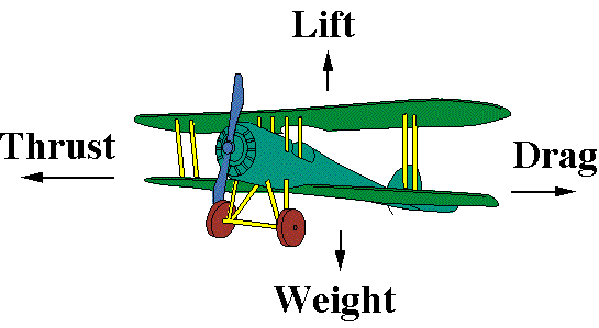
Thrust and drag oppose each other in the horizontal, while lift and weight oppose each other in the vertical. If all four are balanced, the aircraft will fly straight and level at a constant speed, and changing the strength of one of these forces, will often affect another.
Thrust
The simplest of the forces to explain - in powered aircraft this comes from the engine, and as both piston and turbine ones are air breathing, the performance of either will depend on altitude. At higher altitudes, the air is thinner so the oxygen content in a given volume will be less. The oxygen is required for the fuel to burn and if there is too little of it, the engine may stop working completely.
How efficiently an engine operates depends on the fuel-air ratio. If the fuel flow is too high compared to the oxygen, the fuel will not burn completely.
Piston engines often require manual adjustment of the fuel-air mixture to ensure efficient fuel burn. Although the "perfect" (stochastic) mixture is often striven for, in which there is just enough oxygen to burn all the fuel, leaving neither of each out of the exhaust, there are benefits of running the mixture in either "rich" (fuel heavy) or "lean" (air heavy) ratios.
In general, full rich mixtures will produce the most power close to sea level and will often be used at takeoff. Fuel rich also has the benefit of keeping the engine cool, as the un-burned fuel acts as a coolant. Running in this configuration is not the most efficient in terms of fuel consumption however.
Leaning the mixture so that more air than is required to burn all the fuel is flowing through the engine is more fuel efficient than running rich, but will lessen engine cooling.
For an air breathing turbine engine, controlling the fuel-air mixture manually would be near impossible and rather dangerous to do, so this is controlled automatically by a barometric fuel flow controller.
Lift
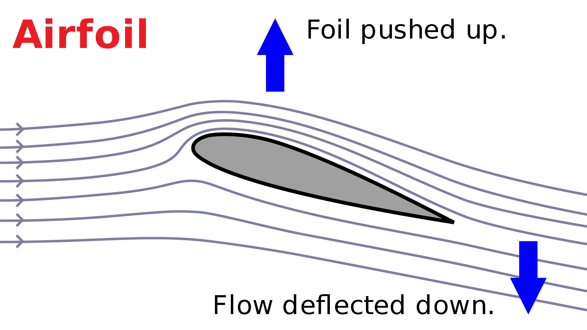
In normal flight, lift is generated by the wings, which are airfoils. Airfoils (or Aerofoils) are of a specific geometry that produces lift by causing a pressure difference between the air flowing over the top of the airfoil, and the air flowing below it. This imbalance is caused by the effective curvature of the airfoil. Air flowing over the top of the airfoil is of lower pressure than the air below, and one can think of the airfoil as being "sucked" towards the low pressure above, which produces a lift force. This is known as Bernoulli’s principle.
Or, more simply, one can also think of the airfoil directing the flow of air downwards, which produces the reaction force of the foil being pushed upwards.
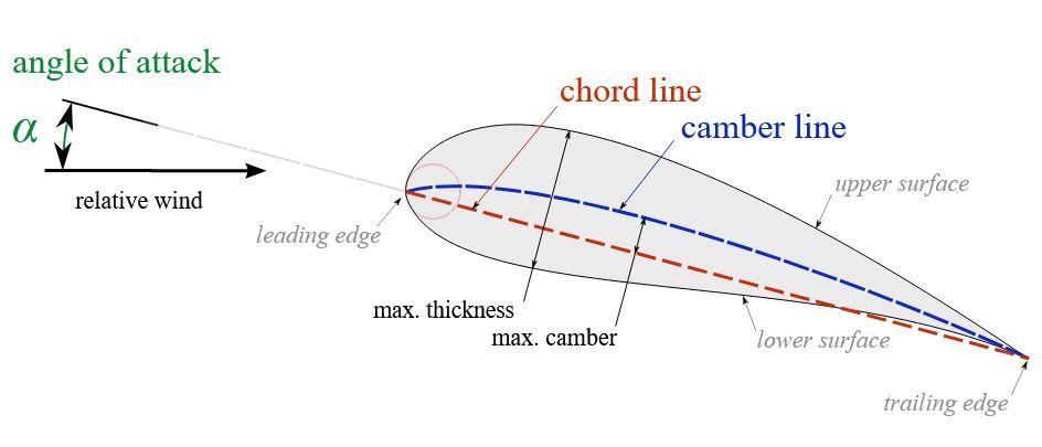
An important variable when talking about lift and drag is the angle of attack (AoA). This is the angle between the chord line (the straight link between the front and rear edge of the airfoil) and the direction of the airflow. If this angle is small, the airfoil is aligned closely to the direction of the airflow, so it does not deflect the direction of the air very much, meaning drag is minimal. If the angle is large, then the airflow will be re-directed by a significant amount, causing more drag. The interplay between drag, lift and AoA is complex and often counter-intuitive. Many aviation accidents happen due to erronous interpretation of the lift-drag-AoA situation, and choosing a course of action that actually makes things worse. For instance, if your aircraft is on a collision course with the ground, it is often intuitive to pull back on the controls to pull the nose up. If however, the primary issue is lack of lift, this increase of AoA will increase drag and make the aircraft's rendezvous with the Earth even more certain.
Airfoils require smooth, non-turbulent airflow over the surfaces to operate effectively. This type of airflow is called Laminar flow. If the speed over the airfoil is too slow, or the angle of attack is too high, it becomes turbulent. The lift force is greatly reduced, or killed completely. If lift is effectively lost, this is a stall.
Control surfaces such as ailerons, elevators and the rudder cause a change in direction or attitude of the aircraft by redirecting the airflow as it leaves the airfoil. For roll, the ailerons move in opposite directions, deflecting the airflow up on one side, and down on the other. This asymmetric force causes the aircraft to roll about its nose-tail axis. Elevators are usually situated on the tail and move synchronously to direct the airflow up or down. This lifts up or pushes down the tail, causing the opposite to happen to the nose as the aircraft pivots about the center of mass. For example: Stick pitch back → elevators up → airflow directed up → force on tail down → nose up → pitch up of the aircraft.
Any surface that produces lift, also produces drag. Airfoils are designed to produce far more lift than drag under nominal conditions, but the lift/drag properties can be modified by moveable aerodynamic and high-lift surfaces such as flaps, slats, spoilers and airbrakes.
- Flaps are usually located on the trailing edge (rear) of the wings and deploy downwards to increase the effective curvature of the wing. This increases the lift force, which lowers the stall speed of the airfoil, but introduces more drag.
- Spoilers disrupt the airfoil over the tops of the wings, which greatly reduces lift. This allows the aircraft to descend without gaining too much speed.
- Slats deploy from the leading edge (front) of the wing and are used to increase lift and decrease the stall speed of the aircraft. They are particularly useful during high angle of attack maneuvers. As with flaps, they also increase drag.
- Airbrakes serve one primary purpose: massively increase drag and decelerate the aircraft.
Drag
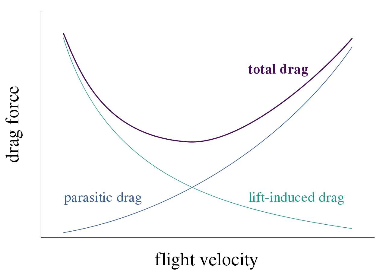
The net drag force experienced by an aircraft is actually made of a few different components. These are the following.
Parasitic Drag
It is the resistance on an object moving through a fluid. In aviation, it is the drag due to the shape and surface of the airframe in contact with the flow of air. The shape of the object will alter the drag coefficient, the more aerodynamic the object is the less drag created. The size will alter the surface area of the object, so the bigger the plane is, the more drag is created. Finally, the speed will increase exponentially the amount of drag created by an object of the same shape and size.
The main factor in parasitic drag is the speed : the faster you go, the higher the parasitic drag.
Induced drag
This is the drag resulting in the redirection of air flow around lift generating surfaces. As we mentioned, lift is generated by a pressure differential between the top and bottom of the wing. As the air flows over the surface, the air below the wing flows outward toward the wing tip and then upwards and inwards around the wingtip to equalize with the lower pressure on the upper surface of the wing. This create wingtip vortices (and wake turbulence). A little known fact is that those vortices are a source of drag: the induced drag. That drag is worse at high angle of attack, on shorter wings and on square wings. Elliptical or tapered wing tips can reduce the amount of induced drag, as can the fitting of winglets.
Wave drag
Drag becomes a lot more complicated when approaching the speed of sound. Air starts to become compressed into shock waves, resulting in very large drag forces. This type of drag on transonic and supersonic aircraft is know as wave drag. For an aircraft traveling close to the speed of sound, the wave drag forces are very complex as the airflow may be supersonic across some edges and surfaces, and subsonic across others. The speed at which supersonic airflow begins to appear on the airframe is known as the lower critical mach number. The upper critical mach number is the minimum speed at which all airflow becomes supersonic. Between these two critical mach numbers, the aircraft is in the transonic regime.
Many non-supersonic aircraft, such as modern airliners, routinely cruise above the lower critical mach number, so even though the aircraft is subsonic, supersonic airflow can occur, and the effects of wave drag must be taken into account. Design considerations such as fuselage cross section, wing shape and the installment of anti-shock bodies help to reduce wave drag.
Speed
For aircraft, speed is a little more complicated than just how fast you are going, because there is more than one way to measure it, and more than one thing to measure it relative to!
Ground Speed
How fast an aircraft flies across the ground is known as "Ground Speed" (GS) This tells you how long it takes to get from point A to point B on a map. It's useful for planned waypoint navigation and Time on Target (ToT) calculations. GS is independent of wind speed or altitude, although these things will affect the thrust required to maintain a given GS.
True Air Speed
True Air Speed (TAS) is how fast your aircraft is moving relative to the air around it. If the air is completely still, and you are flying level with the ground, the TAS is the same as GS. If however, you have a tail wind of 10kts and you are traveling with a ground speed of 150kts, then your TAS is 140kts. This is because the air is "moving with you" at 10kts, so you are moving through it slower than you are moving across the ground. Think of it as kayaking down a river. If you just let the river carry you along at the speed of the water, your speed with respect to the water is zero (akin to zero TAS) but the river bank will be flying past at whatever speed the water is carrying you (akin to GS).
Unlike the kayak, aircraft operate in three dimensions, so if the air is completely still but you are in a vertical dive of 150kts, then your GS is zero, but your TAS is 150kts.
TAS does not depend on altitude, only the speed at which you are moving relative to the air.
Indicated Air Speed
Inidicated Air Speed (IAS) brings in another element. Like TAS, IAS depends on the speed you are moving relative to the air around you, but it also depends on altitude. This is because IAS is determined by measuring the dyanmic pressure of the air. Higher speed = higher pressure, but also higher altitude = lower pressure. Both components affect pressure, and therefore IAS.
This means that in reality, IAS is not a speed at all. It does not tell you how fast you are moving through the air, and it does not tell you how fast you are moving across the ground, yet it is the "standard" indicator of speed in the cockpit. Why so? Because how an aircraft performs - the lift it generates and the drag is incurrs, depend on air pressure. This means that if your aircraft has a stall speed of 90kts IAS, then it will always be 90kts, whether at an altitude of 200 ft or 20000 feet. The aerodynamic performance of an aircraft is constant with IAS. If you were flying with just a TAS indicator, and you know the stall speed is 90kts at sea level, at altitude, the TAS stall speed will be much higher because the air is less dense. The same goes for maximum speed of flap deployment, or turn rate of your aircraft. Since IAS scales with altitude, these properties are constant when measured with IAS.
This also means that, assuming no wind, 250kts IAS (called KIAS when measured in knots) close to the ground is about 250kts GS. However, 250 KIAS at high altitude will mean a much higher GS. This demonstrates one reason why flying at high altitude is more efficient. For the same IAS, you get from A to B quicker at higher altitude but with the same amount of drag and lift.
Mach Number
Mach number is the ratio between the flow velocity past the aircraft and the local speed of sound, i.e, the ratio of the TAS of the aircraft to the local TAS of sound. Therefore if the aircraft is traveling at exactly the speed of sound, the mach number is 1.
The speed of sound however, depends on temperature. The higher the temperature, the faster the speed of sound. Mach number will therefore vary significantly with altitude due to the difference in temperature.
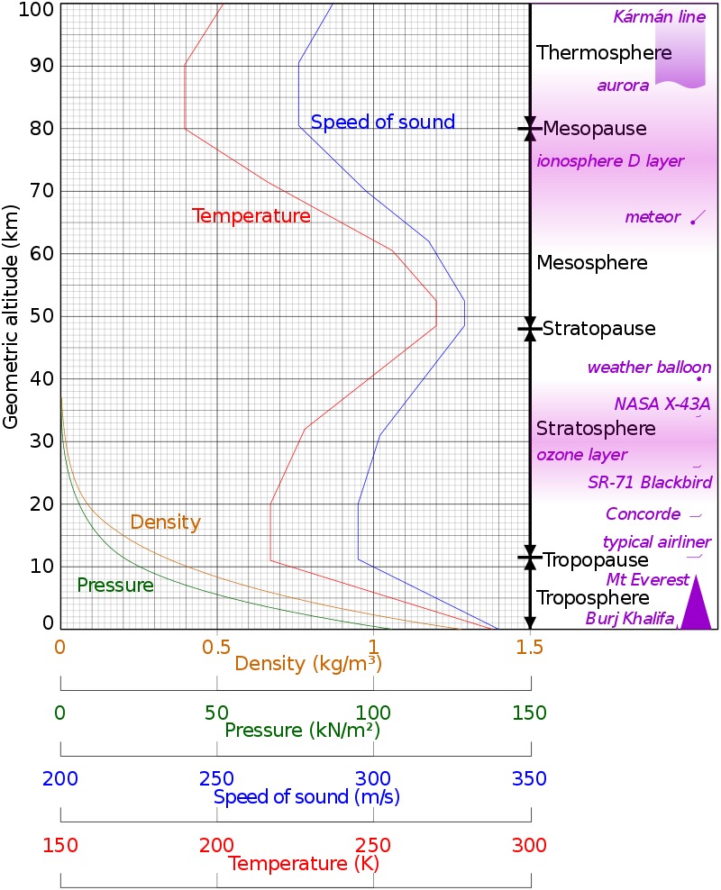
Unless you regularly spend time at the controls of a U2, most of your flying will be within the Troposphere. As we can see from the figure above, temperature decreases as altitude increases up until the Tropopause at ~20,000m (65,000 feet) and therefore so does the speed of sound. This means, in normal weather conditions, your mach number will be greater at altitude than close to sea level, for the same TAS.
Turns
Turning the aircraft is simple. Roll into a bank, and control the rate of the turn with the pitch - but coordinated turning is a little more difficult. Especially with the absence of sensory feedback in flight sims. Coordinated flight involves turning without introducing any skid or slip. This is achieved by coordinating aileron, elevator and rudder control.
When the turn is coordinated, the occupants of the aircraft do not perceive a bank from the forces acting on the aircraft. That is to say, any net force from the turn is always pointing straight down relative to the aircraft. All that appears to change is the magnitude of the force of gravity and not the direction. If the turn is uncoordinated, it can result in either a skidding turn, where the aircraft's tail is skidding outside of the turning circle, and is often a consequence of too much rudder, or a slipping turn, where the aircraft's tail is slipping inside the turning circle due to not enough rudder.
Pilot comfort is not really a priority when it comes to flight sims, but properly coordinating turns also results in much less drag, as the fuselage is aligned with the airflow for the duration of the turn.
Coordinated turns can be practiced in any aircraft that has a turn and slip or a turn coordinator instrument in the cockpit. (Note: Modern aircraft with Fly-By-Wire or Flight Control systems might coordinate flight for you!)
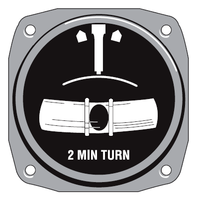
In the turn and slip indicator shown above, the bottom portion (the inclinometer) displays how coordinated your turn is. It is coordinated only if the ball remains in the center for the duration of the turn.
The greater your bank angle is during a coordinated turn, the greater the downward force is that the pilot experiences. This force is essentially the net sum of the apparent centrifugal force of the turn, the weight of the aircraft and the force of lift. This is the origin of the "g-force" experienced during high speed and tight turning.
Now with a bit of extra knowledge on the principles of flight, you can proceed to the first chapter of the BFM fundamentals guide: